


The Building Probable Primer to BIM
What is BIM and why should I care?

BIM is big business. The global BIM industry was valued at 6.57 billion in 2022, set to grow to 21 billion by 2032. To some, BIM is already changing the face of building design and construction management. But for everyone else, what is BIM and why does it matter?
Building reality
Buildings are a great communal feat. Primitive structures have been around for as long as we have. They evolved with us, a necessity to life. To protect us, buildings are larger than us, requiring more than one of us to build.
The act of building is an act of organization and communication. Each worker must have an understanding of what the building looks like and how their task fits within the overall whole. Successful buildings depend on how this part to whole relationship is communicated, understood, and agreed upon.

Drawings are how this communication happens. Within a set of architectural plans is a visual language designed for alignment of what needs to be built and what will be built. Like written language, this agreement is built on a shared mental model of what the drawn symbols represent. For common buildings like wood framed houses, the drawings may not require much detail. Two lines for a wall is all that’s needed between the architect and builder to agree on what to build. For novel buildings, drawings have to be much more detailed. Some things that can’t be left to open interpretation.
Producing drawings through drafting
While all art communicates, technical drawings communicate with specificity. Technical drawings are beautiful, but their goal is the accurate communication of a building idea. This is what differentiates artists from drafters. Artists experiment and evoke, drafters dissect and describe. Artists break rules, drafters need rules.
Technical drawings are used to build real physical things. To make drawings the same size as the thing they represent is sometimes near impossible. Imagine the schematic for tiny cell phone parts or elevations of a skyscraper. Drawings need to be drawn at an enlarged or reduced size while accurately conveying what they represent. These are referred to as “scaled drawings.” A scale can usually be found at the corner of a drawing. For example in 1:200 scale, 1/16th inch distance on the page represents 1 foot in distance of the building design.
 - ArchiMash.com")
Another foundational aspect of technical drawing is that it’s often drawn in orthographic projection. This is different from perspective drawing, in which objects “closer” to the viewer are drawn larger than what’s farther away. To match what is drawn to the intended real physical size, the reader has to measure the drawing, and then convert the measurement to real world size. Perspective makes sense when you are portraying what the viewer might see, but we can imagine how this might not be so great at communicating size, ratio, and the relationship of building parts. To maintain the ratio of dimensions, parallel lines in the real world are represented as parallel lines on an orthographic drawing. The scale is preserved anywhere on the sheet, one scale conversion works for the whole page.

In architectural drawing, there are three common drawings that represent different aspects of the building whole, the floorplan, the section, and elevation. People are most familiar with the floorplan. It’s drawn as if the building is sliced parallel to the ground looking down. This view shows how the rooms are partitioned and how one might move around the floor of the building. The section is similar to the plan but is cut perpendicular to the ground with the view looking to one side. This view shows vertical relationships; how structure sits on top of each other or how stairs link spaces across floors. The elevation shows a head on view of the exterior of the building. It shows what the building looks like facing the street, the arrangement of windows and the type of exterior finish.
There’s of course many other types of drawings that go into describing a building. Reflected ceiling plans, site plans, section details, plumbing and electrical plans, or circulation diagrams; each is a different type of drawing for a different slice of the building idea. To describe a part of the building, an Architect needs to dissect the idea into many different drawings. To build that part of the building, a Builder needs to take those drawings, and reassemble the slices into a coherent whole. For complex buildings, drawing sets can be hundreds of thousands of pages, requiring the work of whole teams of drafters.
Drafting and drawing production

As buildings get more complex, more and more drawings are needed to describe the full idea. The production of architecture design is essentially the production of drawings. Rooms full of people worked on interrelated drawings that are compiled into a drawing set.
To help drawings follow the rules we talked about before, many tools were essential in making them accurate and repeatable. The biggest is a large table that can be angled towards the drafter. On this table spans a large horizontal ruler that moves parallel to the table. It is appropriately called a parallel rule. This parallel rule is essential for the quick execution of accurate parallel lines that form the basis of orthographic drawings. From these parallels, other lines are constructed using a set of angled and curved rulers.
Another important tool is the scale rule, used to quickly measure scaled distances on scaled drawings. Instead of typical distance, the ticks on this ruler are labeled according to the scaled distance. For example, a 1:200 scale rule will be labeled 1 foot for every 1/16th of an inch.

Drawing production has many other specialized tools to help with the physical limitations of making marks on paper. Drawings must be scaled, which means you can draw larger parts smaller, or smaller parts larger, but rarely one to one. Another limitation is using 2D drawings to describe a 3D object. You have to dissect the whole and capture them in different parts on different sheets. You can never capture the entire building in one place.
Digital drafting
CAD stands for Computer Aided Design. Due to the versatility of computers and the many things that need to be designed in this world, this can mean many things. In AEC (Architecture, Engineering, and Construction), CAD often refers to AutoCAD, the industry standard digital drafting tool. Here, I’m going to use CAD as a generic term to refer to any digital drafting tool.
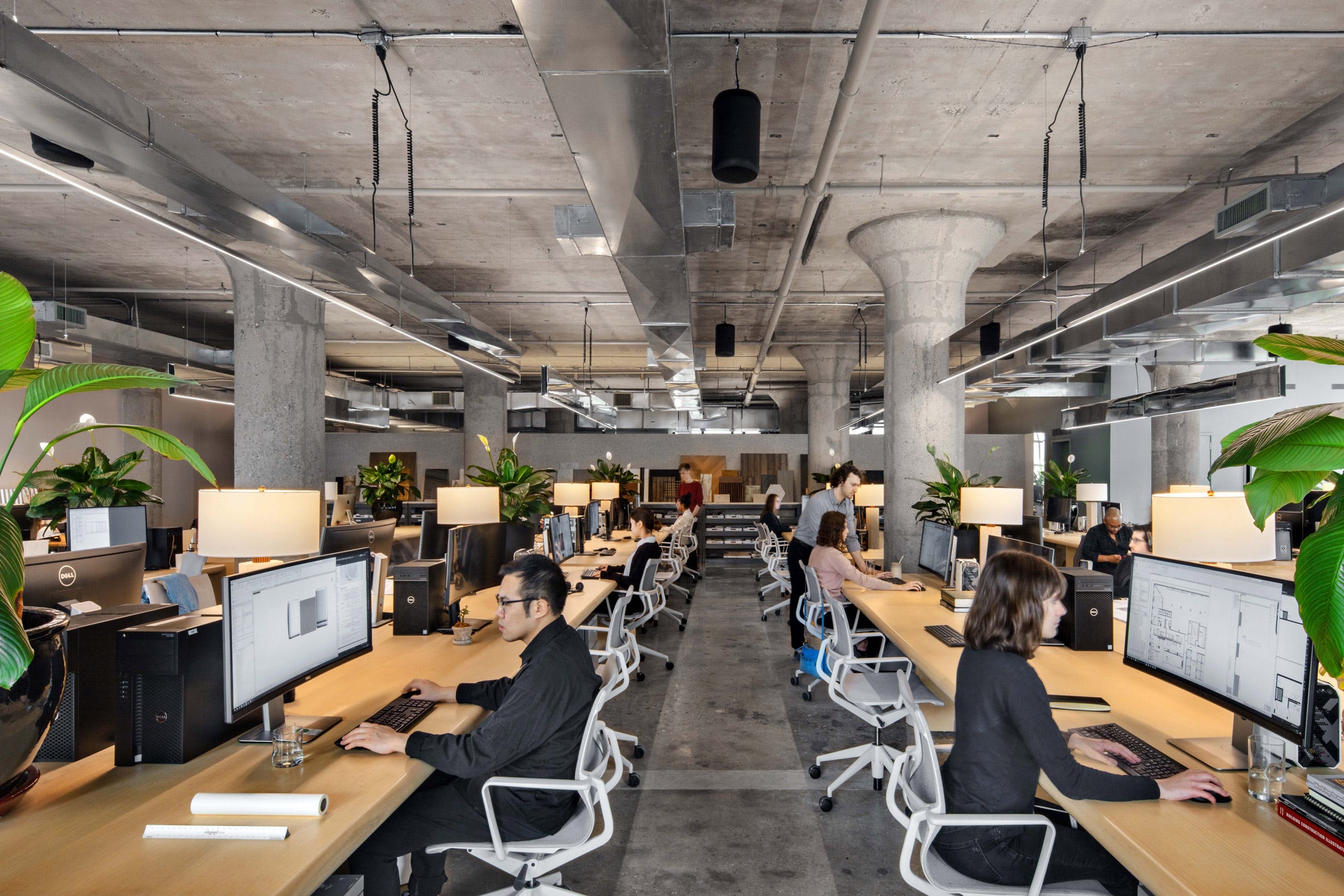
In most offices today, the production of drawings no longer happens with large angled tables and parallel rules. It happens on screens with CAD. Even though digital tools introduced a new level of efficiency to drawing production, the process remains largely the same. Building ideas are described in drawings, a set of which is the final product of the production process. Architecture offices today are not that different from those in the age of drafting by hand. Drafters still work in a sea of desks, just with screens and ergonomic chairs.
Because CAD happens in a digital space on an infinite canvas, the units of the drawing can be one to one to real world units. Instead of using a scale rule to make scaled markings, the whole drawing can be scaled digitally. Printing at 1:200 and 1:50 can happen from the same drawing, just with some menu configuration.
2D CAD resolves our need to scale while drawing, but it doesn’t solve the issue of using 2D to represent 3D ideas. When a particular part of a design changes, the lines need to be updated to match this new change. This means changing the same part across plans, sections, elevations, and any other related drawing. It’s easy to delete and redraw in CAD, but it is still laborious and error prone. If you miss an update, the drawing set now has conflicting information. Mismatched drawings will be confusing when trying to read the building. Worse yet, it could lead to the incorrect thing being built.
A faithful digital representation of the physical world
Computers are powerful tools for generating representation. The digital world is not subject to the same limits of physical drawings and models. Beyond just three dimensions, we can even construct progressions through time and optionality. This changes the paradigm we’ve described so far, where a building idea is dissected and represented through 2D drawings. In a 3D digital world, a building can be faithfully represented and explored at one to one scale.
There’s a wide range of CAD modeling tools out there that can be used to model representations of real world objects. Instead of two lines to describe a wall, you can model out the whole volume. For buildings, you could model out every stud, every door, every chair. The only limitation is the power of the computing software and hardware.
The final product is still a drawing set, but how we get there is different. Instead of constructing drawings, they are extracted from the model. A plan or section is truly cut from the digital building.
This completely changes the process of design production. Instead of drawing many drawings that represent the whole idea, you create a 3D representation of the whole idea from which drawings are extracted. CAD becomes more than a drafting tool, it changes the way we reason about buildings.
With 3D modeling, CAD solves many of our problems. Building ideas can be constructed one to one in digital space. Individual drawings are still important, but the model is a much richer representation of the building idea. Production shifts from drafting to modeling.
There’s still one major hurdle that we’ve yet to solve. Why are we making drawings in the first place? The goal is to align many people around the part to whole idea in order to realize a building in the real world. This requires us to agree that what’s drawn means the same to all of us. In a 2D drawing, an object is represented by lines. Two lines mean a wall, but it could also mean a door, a window, or a change in floor surfaces. This same problem exists in 3D, a box can be a cabinet, an elevator core, or a toilet I’m too lazy to model out. The geometry may be interpreted differently by different people.
 : r/engineering")
Disagreements in what things are in a drawing or model means happens all too often. What makes perfect sense to me may be incomprehensible to you. CAD or not, communicating what lines represent is still a big problem.
Building in the information age
If a computer allows us to construct a faithful one to one model of an unbuilt building, why can’t we layer on even more information? After all, a digital model is just information, and there’s nothing stopping us from adding more information to make things crystal clear.
BIM in the context of this post stands for Building Information Model. There are other things BIM can stand for, and BIM is largely a marketing term from Autodesk to sell Revit. But, it’s the prevalent term in industry, so we’re going to go with it here.
So far, we’ve established that 2D and 3D representation is used to communicate building ideas to align the collective effort of the many people it takes to build that idea into a real building. They are “representative” because the drafter/modeler needs to communicate the idea as a representative drawing/model. The builder needs to reconstitute the building idea using the many forms of representation. Representation leaves room for interpretation, and errors in interpretation lead to disagreements, disagreements create a costly gap between what is intended to be built and what is actually built.
The building information model takes the 3D model a step further by attaching information to the geometry. The two lines on a page that needed mental translation to become a wall are now labeled a wall. This may seem like a mundane addition, just adding tags to geometry. However, this simple addition creates a cascade of outcomes, transforming how building ideas are built.
What happens when two walls meet? When drawing, it’s up to the drafter to resolve this intersection. Brick walls intersect differently than wood framed walls. When the idea changes and a wall needs to be moved, drawings need to be redrawn, the intersection re-resolved in lines. With BIM, the software, knowing that two wall elements are meeting, can automatically handle the resolution of this intersection. When the wall needs to move, the software just resolves the new placement.
The same happens when an elevator needs to pierce through many floors, or when columns need to shift, when ducts need to move. A building as an unbuilt idea is a fluid set of requirements and relationships. Resolving them in a one to one representation of the building, with software that understands what real world components the element represents, creates a faster, more detailed, and higher fidelity resolution of the building idea.
BIM is still a representation. Through software that understands the real world rules of buildings, a building idea can be constructed first in digital space, its contradictions solved, its relationships resolved, before drawings are ever extracted.
This is a fundamental change in the way architectural production works. Instead of descriptive technical drawings, an information model is produced. With this information model, any number of drawings can be extracted without extra physical labor. Because this model is rich with information and knows what real world elements its geometry represents, it opens the door to a higher fidelity form of design communication. A wall is a wall is a wall.
BIM, Buildings, and Beyond
We covered a lot of things in this primer.
Buildings require the collaborative effort of many. To align these efforts, a building idea needs to be accurately communicated.
Technical drawings, as a representation of building ideas, are used to communicate the complexity of what needs to be built to people who need to build it.
CAD allows us to draw at one to one scale, making us more efficient at producing drawings. However, because drawings are symbolic, geometry is still open to interpretation (and misinterpretation).
BIM combines geometry with information about what it represents in the real world. This not only clarifies what the geometry is supposed to represent, but also allows the model to “self resolve” based on algorithms about the objects and the real world rules that govern them.
We walked through the role of drawing production and how BIM has the potential to completely change that paradigm. In future posts, we will discuss in more detail how this new baseline built upon information and data creates new opportunities for what we can do with a building idea.
If you’re interested in these future posts, please subscribe to this newsletter